The Ghost in the Data: Precision Drive Shafts for Dutch Torque Test Benches
If you run a propulsion lab in the Brainport region or manage a quality control rig for industrial pumps in Rotterdam, you know the scenario: You are running a durability cycle, crossing the zero-torque threshold, and suddenly your torque transducer readings show a spike that shouldn’t be there. It’s not your sensor. It’s not the specimen. It’s your drive shaft. In the world of Precision Test Benches, the standard industrial universal joint is a liability. It has mass, it has backlash, and worst of all, it introduces non-constant velocity (the Cardan effect) that corrupts your data.
Modern testing in the Netherlands—driven by the rapid shift to electric mobility and high-efficiency drivetrains—demands a new standard. We are no longer looking at 3,000 RPM diesel engines; we are looking at 18,000 RPM e-motors where “vibration” isn’t just noise; it’s a catastrophic failure waiting to happen. To capture true data, your driveline must be invisible. This requires ゼロバックラッシュ, infinite fatigue life, and dynamic balancing that borders on obsessive.
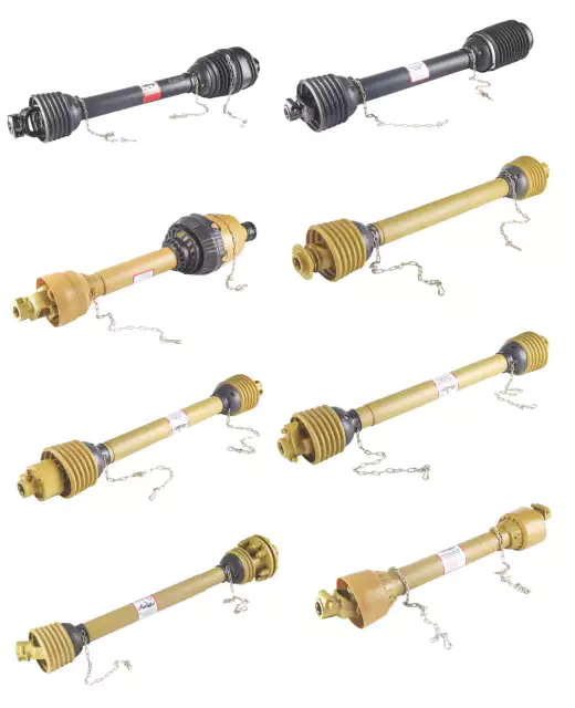
Engineer’s Log: The “Hysteresis” Headache
“I was called into a university lab in Delft last winter. They were testing a new micro-turbine design. The students were baffled because their efficiency calculations were fluctuating by 4%. I looked at their coupling: a standard splined automotive shaft. I explained that every time they reversed load, the microscopic play in the splines created a ‘dead zone’ or hysteresis. We swapped it for our Titanium-Bellows Zero-Backlash Shaft. The efficiency curve smoothed out instantly. Precision isn’t just about the sensor; it’s about the mechanical connection to that sensor.”
The Dutch Challenge: Precision Meets Speed
The Netherlands is unique. We have a dense concentration of high-tech R&D facilities (from ASML’s suppliers to DAF’s proving grounds) packed into a small area. The expectation for calibration accuracy here is among the highest in Europe. A test bench operator in Eindhoven doesn’t just want a shaft that spins; they want a shaft that acts as a perfect torsional stiffener.
The problem with traditional cardan shafts in these applications is two-fold: Velocity Fluctuation そして Residual Imbalance. Even a perfect U-joint creates a sinusoidal speed change twice per revolution if there is an angle. At 15,000 RPM, this excites the natural frequencies of your test bed, leading to ‘ghost’ vibrations in your FFT analysis. Our solution uses Flexible Disc Packs (Lamellae) または Metal Bellows. These designs accommodate misalignment through the elastic bending of metal, ensuring true Constant Velocity (CV) and zero wear, with no moving parts to generate play.
Configure Your Precision Shaft
Technical Specifications: EP-TestBench Series (High Precision)
In the lab, “approximately” is a dirty word. Below are the generated parameters for our EP-Precision (EP-P) Series, specifically engineered for the rigorous demands of Dutch test facilities. Note the tight tolerances on runout and balance.
| パラメータID | 仕様説明 | 値 / 範囲 | ユニット |
|---|---|---|---|
| TB-01 | 公称トルク(Tn) | 20 – 2,500 | ナノメートル |
| TB-02 | Max Transmissible Torque | 3,800 | ナノメートル |
| TB-03 | 最大回転速度 | 18,000 – 24,000 | 回転数 |
| TB-04 | Torsional Stiffness (Ct) | 45 – 320 | kNm/rad |
| TB-05 | ダイナミックバランスグレード | G 2.5 (Std) / G 1.0 (Opt) | ISO 1940 |
| TB-06 | 反発 | 0.00 (Zero) | 学位 |
| TB-07 | Angular Misalignment | 1.0 – 2.0 (per element) | 学位 |
| TB-08 | 軸方向補正 | ± 1.5 – ± 4.0 | んん |
| TB-09 | Radial Misalignment | 0.15 – 0.4 | んん |
| TB-10 | チューブ材質 | Carbon Fiber / Aluminum | – |
| TB-11 | Bellows Material | Stainless Steel 316Ti | – |
| TB-12 | ハブ素材 | High Strength Aluminum | 7075-T6 |
| TB-13 | Moment of Inertia (J) | 0.0025 – 0.009 | kg·m² |
| TB-14 | Critical Speed (1st Bending) | > 28,000 | 回転数 |
| TB-15 | Length (L) | 350 – 1500 | んん |
| TB-16 | 動作温度範囲 | -40 to +250 | °C |
| TB-17 | 接続タイプ | Clamping Hub / Flange | – |
| TB-18 | トルクリップル | < 0.05 | % |
| TB-19 | 重さ | 2.5 – 8.5 | kg |
| TB-20 | 軸方向剛性 | Low (Protects Sensors) | N/mm |
| TB-21 | 疲労寿命 | Infinite (at rated load) | Cycles |
| TB-22 | Clamping Screw Grade | 12.9 | メトリック |
| TB-23 | 表面処理 | Anodized / Nickel Plated | – |
| TB-24 | Lateral Stiffness | 高い | N/mm |
| TB-25 | Sensor Integration | Space for Torque Flange | はい |
| TB-26 | Safety Rating | Burst Speed > 1.5x Max | – |
Engineering for “Zero”: The Material Science
When you are testing a transmission’s durability, you are simulating years of abuse in a few weeks. The drive shaft cannot be the weak link. We utilize 炭素繊維複合チューブ for longer spans. Why? Because the specific stiffness of carbon fiber is typically 3-5 times that of steel. This pushes the “whirling speed” (critical frequency) far above your operating range.
By bonding these composite tubes to precision-machined aluminum hubs with Titanium or Stainless Steel Disc Packs, we create a driveline with extremely low inertia. Low inertia is critical for dynamic testing (like simulating a car driving over a curb) because it allows the dynamometer to change speed rapidly without the drive shaft acting as a flywheel and dampening the response.
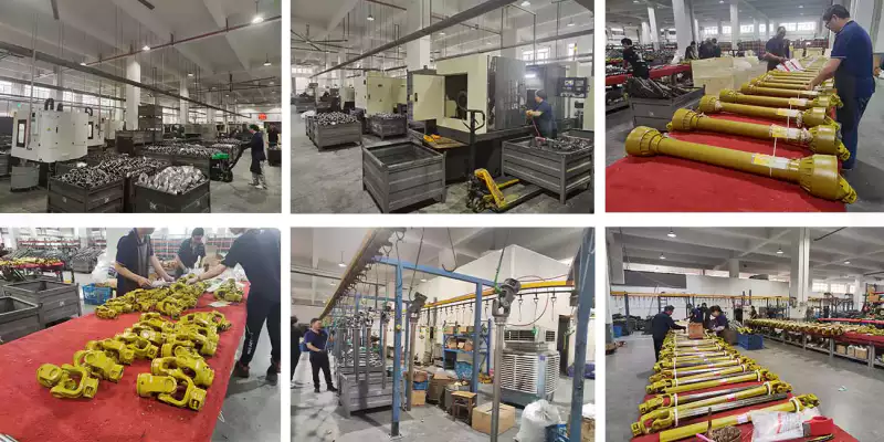
Success Story: The Automotive Component Lab in Helmond
課題: A Tier-1 automotive supplier at the Automotive Campus in Helmond was testing a new E-Axle system. At 12,000 RPM, their existing steel cardan shaft was resonating, causing the torque telemetry to become unreadable. The vibration was also damaging the expensive torque flange sensor.
私たちのソリューション: We performed a modal analysis and designed a custom Carbon Fiber Shaft with High-Damping Disc Elements. The carbon fiber tube was tuned to have a natural frequency of 600 Hz (36,000 RPM equivalent), well outside the test window.
結果: The resonance disappeared. The signal-to-noise ratio on their torque data improved by 200%. The client was able to complete their 500-hour endurance run without a single shutdown.
ブランド互換性と法的免責事項
In the high-precision world of test benches, you will encounter components from KTR, フォイト, マイヤー, GKN、 または レックスノード. These companies set the standard for quality.
However, we offer what they often cannot: Speed of Execution. When a test rig is down, every hour costs thousands of Euros. We can machine custom adapter plates or balance a specific shaft length in days, not weeks, helping you keep your validation schedule on track.
From the Lab to the Field: High-Performance Gearboxes
It may seem like a disconnect to jump from 24,000 RPM test bench shafts to machinery, but the engineering principles of Power Transmission Integrity are universal. Ever-Power is also a premier manufacturer of ギアボックス. In the Netherlands, known for its intensive and high-tech farming, the demand for reliability is just as high in the field as it is in the lab.
We apply the same rigorous quality control—case hardening, precision gear grinding, and dual-lip sealing—to our gearboxes. Whether you are building a rotary tiller, a fertilizer spreader, or a TMR mixer, the gearbox is the heart of the machine. We supply:
- Spiral Bevel Gearboxes: For quiet, efficient power transfer at 90 degrees.
- スピードアップ装置: For driving hydraulic pumps or fans from a standard PTO.
- 平行軸減速機: For high-torque heavy-duty applications.
If you are an OEM developing a new implement, we can provide a “Power Package”: the PTO drive shaft (matched to the torque requirements) and the gearbox, designed to work together perfectly. This eliminates the common issue of spline fretting caused by mismatched tolerances between the shaft yoke and the gearbox input.
よくある質問(FAQ)
Why use a disc pack coupling instead of a U-joint for test benches?
A U-joint (Cardan joint) creates non-uniform velocity if there is any angle. This means the output shaft speeds up and slows down twice per revolution. In a precision test bench, this velocity fluctuation looks like vibration and torque ripple in your data. A disc pack coupling is a true Constant Velocity (CV) joint, providing smooth rotation regardless of angle.
Can you balance the shaft with the hubs attached?
Yes, for high-speed applications (G2.5 or G1.0), balancing the assembly as a whole is mandatory. We balance the shaft with the hubs and flexible elements installed to ensure that the entire rotating mass is concentric and vibration-free.
What is the lead time for a custom-length test bench shaft?
We understand that R&D projects move fast. For shafts using standard hub interfaces (clamping or flange), we can typically assemble, balance, and ship a custom length within 10-15 business days to locations across the Netherlands.
Do you support on-site installation in the Netherlands?
While we primarily manufacture the components, we work with a network of specialized millwrights in the Brabant and Randstad regions who can perform laser alignment and on-site vibration analysis to ensure your new shaft is installed perfectly.
業界ニュース(オランダ 2026): With the EU’s push for stricter emissions monitoring (Euro 7) and the rapid expansion of hydrogen powertrain research in northern Netherlands, demand for “multi-fuel” engine test benches is rising. These hybrid benches require extremely versatile drivelines capable of handling the torsional vibrations of combustion engines AND the high speeds of electric motors on the same rig.