Precision Drive Shafts for
Back-to-Back E-Axle Test Rigs
The critical mechanical link for closed-loop regenerative testing. Minimize parasitic losses and eliminate resonance in high-speed Dutch endurance validation facilities.
The “Mechanical Fuse” in the Energy Loop
In my 18 years of engineering drivelines for R&D centers—from the automotive hubs near Helmond to the heavy-duty test centers in Rotterdam—I’ve seen the same challenge pop up every time a lab switches to a Back-to-Back (mechanical closed loop) configuration. The theory is brilliant: connect two E-Axles, let one drive, and the other regenerate, and the grid only supplies the losses. It’s the gold standard for endurance testing under the EU’s strict energy efficiency directives.
But here’s the catch most system integrators overlook: the Drive Shaft becomes the battlefield. In a back-to-back rig, the shaft is locked between two powerful electric motors fighting each other. One is in torque control, the other in speed control. This creates a “locked-in torque” scenario where the shaft sees full load 100% of the time, often with high-frequency torque ripples that standard automotive propshafts simply cannot dampen. We’ve seen standard CV joints overheat and fail within 48 hours in these setups because they weren’t designed for the constant axial micro-movements caused by thermal expansion in the closed loop.
The trick is moving away from “off-the-shelf” vehicle shafts. For a stable rig, you need High-Torsional Stiffness to maintain the phase relationship between the two inverters, but enough damping to eat the harmonics. At EVER-POWER, we engineer specific test-bench shafts that act as a precision instrument, not just a connector. We balance them to G1.0 standards because when you are running a simulated highway cycle at 16,000 RPM for 3 weeks straight, even a gram of imbalance will destroy your torque meter bearings.

Visualizing the Link
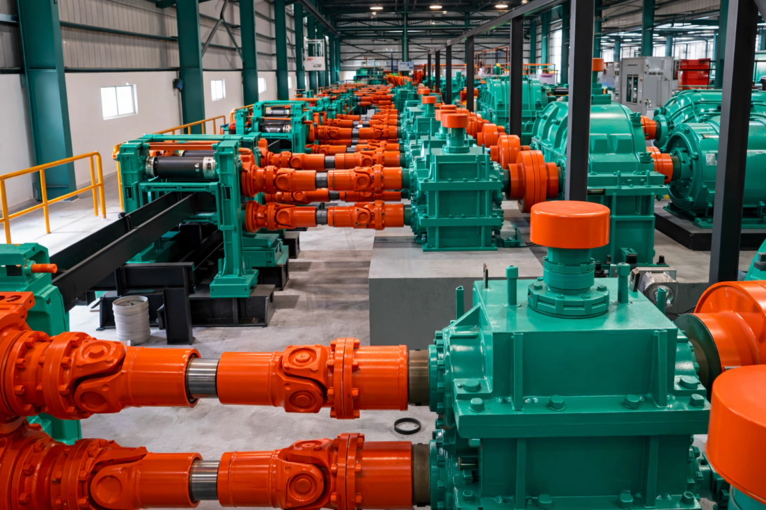
Notice the customized flange adapters. In a back-to-back setup, alignment is everything. Our shafts feature micrometer-precise pilot bores to ensure concentricity between the Specimen (DUT) and the Load Machine.
Core Technology: Surviving the Closed Loop
Resonance Management
In a back-to-back layout, the physical distance between the two E-Axles is often dictated by the mounting pallet, leading to longer shaft requirements. A long steel shaft hits its “whirling speed” (critical frequency) terrifyingly fast. We utilize Carbon Fiber Composite Tubes with tuned filament winding angles. This pushes the first bending mode well above 20,000 RPM, allowing you to run full-speed tests without an intermediate pillow block bearing (which just adds another failure point).
Zero-Backlash Torque Reversal
Endurance cycles involve simulating “Tip-in/Tip-out” maneuvers—rapidly switching from acceleration to regeneration. Standard splines have play (backlash). When torque reverses 50 times a minute, that backlash creates a hammer effect (clunk) that ruins your data and fatigues the shaft. Our Disc Pack Couplings use flexible stainless steel laminae to transmit torque. They have zero backlash, infinite fatigue life, and no wearing parts to contaminate your clean room.
Thermal Growth Compensation
Even with liquid cooling, E-Axles get hot. The casing expands. In a rigid back-to-back setup, if the shaft can’t breathe axially, it turns into a strut, pushing massive thrust loads into the DUT bearings. Our shafts feature Lågfriktionssplines or flexible diaphragm elements designed specifically to absorb this ±5mm of thermal growth without inducing parasitic thrust loads that would invalidate your efficiency measurements.
Technical Matrix: E-Axle Endurance Series
| Parameter | Standard Dyno Shaft | EVER-POWER E-Loop Series | Test Engineer Benefit |
|---|---|---|---|
| Max kontinuerlig hastighet | 6,000 – 8,000 RPM | 18,000 – 25,000 RPM | Validates high-speed EV motor efficiency maps. |
| Balancing Grade (ISO 1940) | G 6.3 | G 1.0 / G 2.5 | Protects sensitive inline torque transducers. |
| Torsionsstyvhet | Medium (Damps vibration) | High (Composite/Disc) | Prevents control loop instability (hunting) between inverters. |
| Glapp | > 0.1 deg | Zero | Accurate simulation of regen-braking transitions. |
| Momentkapacitet | 500 – 2000 Nm | Up to 5000 Nm | Handles the massive instant torque of modern truck E-axles. |
| Material | Welded Steel | Carbon Fiber / Titanium | Low inertia allows faster transient response testing. |
Case Study: 4,000-Hour Endurance Run in Brabant
Utmaningen
A Tier-1 automotive supplier in the North Brabant region (the heart of Dutch automotive innovation) was commissioning a new Back-to-Back rig for a heavy-duty electric truck axle. The setup required a 1.8-meter connection between the drive and load units. Their initial steel shaft installation was vibrating violently at 4,200 RPM due to critical speed resonance, halting the commissioning process and costing €15,000/day in delays.
Lösningen
EVER-POWER engineers analyzed the rotordynamics. We designed a custom Filament-Wound Carbon Fiber Shaft with a diameter of 120mm to maximize stiffness. We integrated precision-balanced disc-pack couplings to handle the 0.3-degree misalignment inherent in their pallet system.
Resultatet
The rig now operates smoothly up to 12,000 RPM (well beyond the truck’s operational limit). The carbon shaft’s damping properties absorbed the high-frequency inverter switching noise, resulting in cleaner torque signal data. The client completed a 4,000-hour continuous endurance run with zero driveline maintenance.
Customization: The Speed of Innovation
In the EV race, waiting 12 weeks for a shaft from a legacy supplier isn’t an option. Your prototype E-Axle dimensions change with every design iteration. We get it.
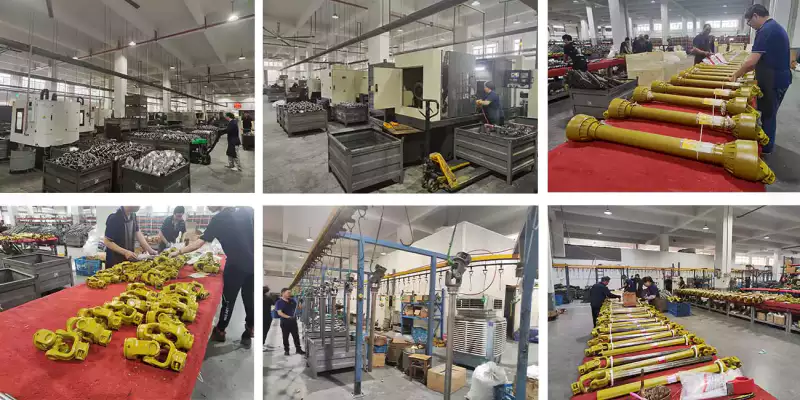
That’s why we established a “Rapid Response” cell for test bench components. We stock high-modulus composite tubes and modular flange interfaces. We can bond, balance, and ship a custom-length high-speed shaft to the Netherlands in as little as 12 working days. We also offer custom adapter plates (e.g., matching a DIN flange on the dyno to a spline on the prototype axle) machined in-house.
Global Market Insight: Top 10 EV Test Bench Component Suppliers (2025/2026)
Reliability in testing infrastructure is paramount. Based on global installations in high-speed E-mobility labs and feedback from test engineers, here are the leaders driving the industry:
- KTR Systems (Tyskland)
- EVER-POWER TRANSMISSION (High-Speed Specialists)
- R+W Coupling Technology (Germany)
- Voith Turbo (Tyskland)
- HZPT DRIVE SOLUTIONS (Integrated Drivelines)
- Mayr Power Transmission (Germany)
- Rexnord (USA)
- EVER-POWER GEARBOX (Precision Gearing)
- Centaflex (Tyskland)
- Reich-Kupplungen (Tyskland)
*Ranking based on R&D investment in high-RPM composites and global test bench market share.