Next-Generation Drive Shafts for Dutch Wind Energy
Engineering Resilience into the Main Shaft, Gearbox, and Generator Links
If you have spent any time dealing with MRO (Maintenance, Repair, and Operations) in the Dutch wind sector, you know that the wind conditions off the coast of IJmuiden or up north near Eemshaven are unforgiving. We have seen it time and again: a perfectly good turbine goes down not because the blades failed, but because the drivetrain couldn’t handle the dynamic torture of gust loads. The connection between the gearbox and the generator—the high-speed shaft—is often the weakest link, yet it is expected to survive millions of cycles of torsional stress. In our experience, many operators focus heavily on the gearbox itself, often overlooking that the drive shaft is the fuse in the system. If your coupling stiffness is off, or if you haven’t accounted for the modal frequencies, you are essentially vibrating your expensive generator bearings to dust.
The trick is understanding that a drive shaft in a wind turbine isn’t just a torque tube; it is a dynamic filter. We utilize advanced मरोड़ कंपन विश्लेषण (टीवीए) to map out the system’s behavior before we even cut metal (or wind carbon fiber). By generating a Campbell diagram, we can visualize where the excitation frequencies from the gear mesh and the rotor passing frequency sit relative to the shaft’s natural frequency. Most maintenance teams don’t realize that simply swapping a steel spacer for a lighter carbon fiber one shifts these natural frequencies, potentially moving a resonance point right into your operating range—or, if done correctly, moving it safely out. It is a balancing act, and getting it wrong means downtime in a season where wind yields are highest.
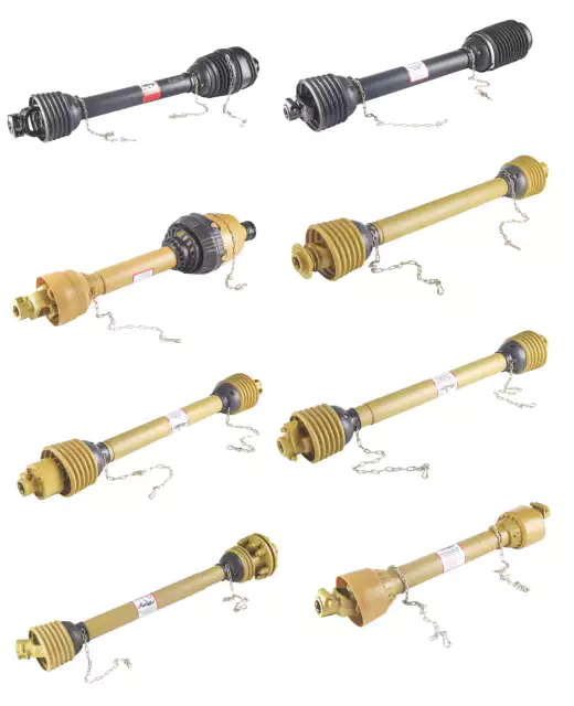
The Case for Carbon Fiber: Weight & Insulation
Let’s talk about weight reduction in the nacelle. Every kilogram you take out of the drivetrain is less stress on the mounting points and less inertia to overcome. However, the real reason we push for carbon fiber center sections in the Netherlands isn’t just about weight—it is about electrical isolation. In modern DFIG (Doubly Fed Induction Generators), stray currents are a persistent headache. If you use a solid steel shaft, you are creating a perfect conductive path for these currents to discharge through your gearbox bearings, causing electrical erosion (fluting). We have pulled apart gearboxes that looked like they had been sandblasted internally, all because of parasitic currents.
By utilizing a filament-wound carbon fiber spacer (or sometimes a glass-fiber hybrid depending on torque requirements), we create an electrically insulating barrier. This cuts the circuit. No current flow means no bearing flute marks. Furthermore, carbon fiber has a specific stiffness significantly higher than that of steel. This allows us to span longer distances between the gearbox output and generator input without requiring intermediate support bearings, which simplifies the nacelle layout immensely. In the humid, salty air of the Dutch coast, removing a bearing point is removing a maintenance liability. It is one less thing to grease, monitor, and eventually replace.
Flexible Couplings and Surviving the North Sea
The coupling elements themselves—usually membrane or disc packs—are where the rubber meets the road (or where the wind meets the grid). We favor high-performance membrane couplings because they offer zero backlash and infinite life if operated within their misalignment ratings. However, the corrosive environment in the Netherlands, particularly in offshore parks or coastal zones like Maasvlakte, eats standard steel membranes for breakfast. Salt spray crystallization can seize the bolts and pit the membranes, creating stress risers that lead to catastrophic failure.
Our approach to offshore corrosion protection goes beyond a simple coat of paint. We utilize specific stainless steel alloys for the membrane packs and apply C5-M rated coating systems to the flanges and hubs. We also integrate condition monitoring ports directly into the shaft design. This allows operators to install wireless torque and vibration sensors that feed data back to the SCADA system. Being able to see a vibration trend spike during a storm, allowing you to shut down before a coupling shatters, is invaluable. It shifts you from reactive firefighting to predictive maintenance.
Technical Parameters: Wind Turbine Drive Shafts
| Feature / Parameter | विनिर्देश सीमा | नोट्स |
|---|---|---|
| नाममात्र टॉर्क (Tkn) | 2 kNm – 500 kNm | Customizable for MW class |
| Max. Misalignment (Angular) | 0.5° – 1.5° | Dependent on membrane type |
| Spacer Material | Carbon Fiber / Glass Fiber / Steel | Filament wound for specific stiffness |
| विद्युत इन्सुलेशन | > 10 kVolts | Standard on composite models |
| परिचालन तापमान | -40°C to +80°C | Suitable for North Sea winters |
| संतुलन ग्रेड | ISO 1940 G6.3 or G2.5 | High precision balancing available |
| संक्षारण वर्ग | C4 – C5M (ISO 12944) | Optional specialized coatings |
Customer Success Story: Retrofit in Flevoland
चुनौती: A mid-sized wind farm in Flevoland, operating 2.5MW turbines, was experiencing repeated generator bearing failures on three specific units. Vibration analysis indicated high-amplitude vibrations at 2x grid frequency, suggesting stray currents and a resonance issue with the existing steel spacer shafts. The downtime was costing the operator approximately €15,000 per week per turbine during peak wind season.
समाधान: EVER-POWER engineers conducted an on-site modal bump test and confirmed the steel shaft’s natural frequency was too close to the operating speed. We designed and manufactured a retrofit Carbon Fiber Composite Link Shaft. This reduced the coupling weight by 60% and shifted the critical speed well above the operating range. Crucially, the composite material provided the necessary electrical isolation.
ये परिणाम: Since the installation 18 months ago, the bearing vibration levels have dropped by 75%, and there has been zero evidence of electrical fluting. The operator has subsequently ordered retrofit kits for the remainder of the fleet, securing long-term reliability for their assets.
Custom Engineering: Not Just Off-the-Shelf
We realize that in the wind industry, “standard” is a relative term. A gearbox retrofit might change the face-to-face distance by 50mm, rendering the stock shaft useless. This is where our factory customization shines. We don’t just stock parts; we manufacture solutions. We can modify flange bolt patterns, adjust spacer lengths to the millimeter, and tune the torsional stiffness of the composite tube by altering the fiber winding angle. Whether you need a single prototype for a test bench or a batch of 50 for a farm-wide upgrade, our manufacturing process is agile enough to handle it. We encourage our Dutch partners to send us their drivetrain drawings so we can run the simulations for you.
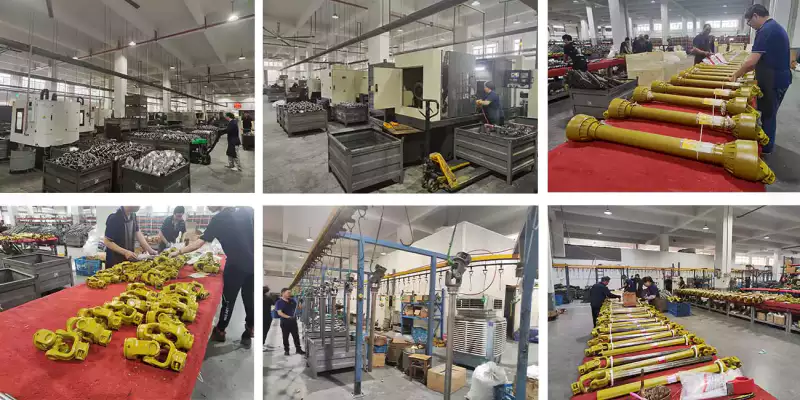
Figure 2: Precision manufacturing of composite drive shafts tailored for wind applications.
अक्सर पूछे जाने वाले प्रश्नों
How quickly can you deliver a replacement wind turbine shaft to the Netherlands?
For standard dimensions, we can often ship within days, but for custom-engineered composite shafts required for specific Dutch wind farm retrofits, our typical lead time is roughly 3 to 5 weeks, depending on the complexity of the flange interfaces.
What is the cost difference between steel and carbon fiber spacer shafts for 2MW turbines?
While carbon fiber options generally carry a premium of 30-50% upfront compared to steel, the total cost of ownership is lower due to reduced bearing wear, no electrical erosion repairs, and longer service intervals, making them the smarter financial choice long-term.
Do you offer installation support for gearbox coupling replacements in offshore environments?
We act as the manufacturing partner supplying the hardware and detailed installation guides, including torque specs and alignment tolerances, but we usually partner with local Dutch O&M service providers who handle the physical offshore installation work.
Can you replicate an obsolete coupling for an older Vestas or Siemens turbine model?
Yes, reverse engineering is a core part of our service; if you can provide the broken sample or the original drawings, we can manufacture a drop-in replacement that often exceeds the original specifications using modern materials.
Where can I find a supplier that understands the C5-M corrosion standards for North Sea projects?
You have found us; we strictly adhere to ISO 12944 standards for our offshore products, ensuring that the coating systems on our steel flanges are rated for the high salinity and humidity found in Dutch coastal waters.