Composite Drive Shafts for
High-Speed EV Motor Test Benches
The critical link for 20,000+ RPM E-Axle validation. Engineered for the automotive innovation hubs of Eindhoven and Helmond. Zero-backlash, ultra-low inertia, and G1.0 precision balancing.
The “RPM Wall” in Dutch Automotive R&D: An Insider’s View
In our 18 years of supporting powertrain testing, we’ve watched the landscape shift dramatically. It used to be that a 6,000 RPM combustion engine test was considered “high speed.” Today, with the explosion of EV development in the Netherlands—driven by the innovative clusters around the Automotive Campus in Helmond—we are routinely seeing requirements for 18,000, 20,000, and even 25,000 RPM.
The problem most test lab managers run into isn’t the dynamometer itself; it’s the mechanical fuse in the middle: the drive shaft. We’ve seen standard steel cardan shafts literally turn into “skipping ropes” (whirling) when pushed beyond their critical speed on a long-wheelbase test bed. Most people don’t realize that as you push past 15,000 RPM, the mass of the shaft becomes your worst enemy.
The trick isn’t just making it stiffer; it’s about Specific Modulus. That’s why for our high-end EV test bench applications, we almost exclusively switch to Carbon Fiber Reinforced Polymer (CFRP) tubes. By dropping the weight by 60% while increasing stiffness, we push the critical speed resonance well above your operating range. It’s not just a component; it’s the only way to safely validate an 800V E-Axle without destroying your torque sensors.

Precision Defined
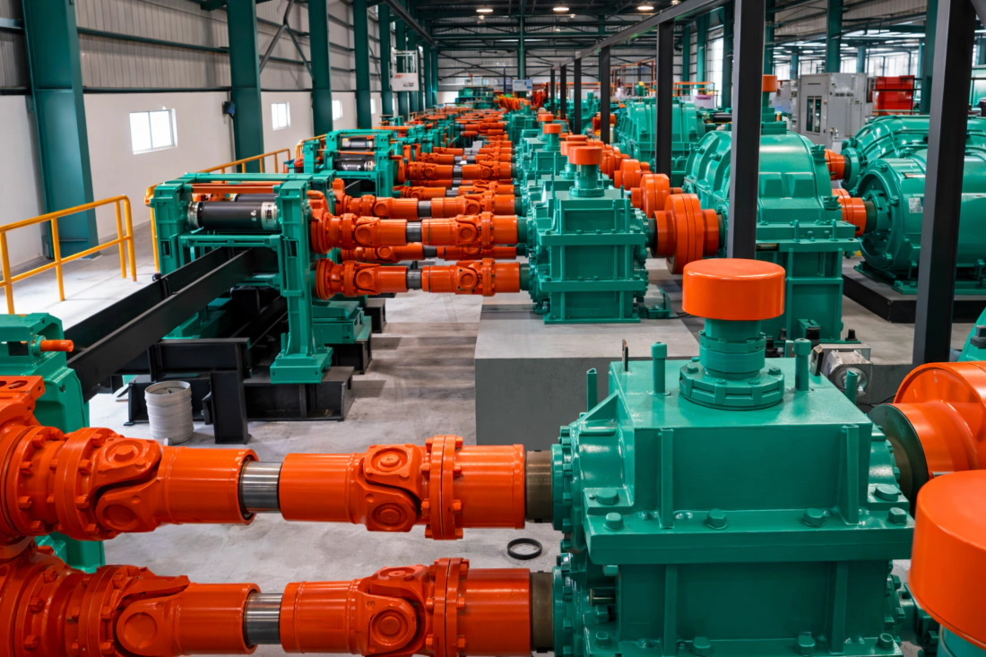
Visualized here is our T-Series High-Speed Coupling. Note the titanium spacer elements designed to reduce inertia. Every gram shaved off the rotating mass improves the dynamic response of your test cycle.
Engineering for the Electric Era
The Vibration Signature
EV motors don’t vibrate like diesel engines, but they have their own demons: Torque Ripple and high-frequency harmonics. A standard industrial U-joint has internal clearances that create “micro-shocks” at 20kHz switching frequencies. We utilize Zero-Backlash Disc Pack Couplings integrated with the shaft. These stainless steel laminae provide infinite fatigue life (if aligned correctly) and transmit torque with absolute angular fidelity.
Composite vs. Steel
Why do we push composite tubes for Dutch test labs? It’s simple math. A 1.5-meter steel shaft might hit its first natural frequency bending mode at 4,500 RPM. A composite shaft of the same dimensions hits it at 9,200 RPM. For an E-Axle dyno running at 16,000 RPM, a steel shaft would need to be prohibitively thick and heavy (destroying bearings), or supported by a pillow block (adding friction). Composite solves this physics problem elegantly.
Thermal Management
In an environmental chamber test at a facility like TNO, temperatures can swing from -40°C to +120°C. We use a specialized bonding agent for the metal-to-composite interface that matches the Coefficient of Thermal Expansion (CTE). This prevents the dreaded “bond line shear” that has plagued lesser composite shafts in extreme thermal cycling tests.
Technical Matrix: EV-Series Dyno Shafts
| Parameter | Steel Series (Heavy Duty) | Carbon Fiber Series (High Speed) | Application Context |
|---|---|---|---|
| Max Rotational Speed | Up to 6,000 RPM | Up to 30,000 RPM | Dependent on length and diameter. |
| Torque Density | High | Medium/High | Steel preferred for low-speed truck dynos. |
| Balancing Standard | ISO 1940 G6.3 | ISO 1940 G1.0 / G2.5 | Critical for protecting high-speed motor bearings. |
| Inertia (J) | High | Very Low | Low inertia allows faster transient testing. |
| Backlash | Standard Spline Fit | Zero (Interference Fit) | Essential for accurate efficiency mapping. |
| Temperature Range | -30°C to +150°C | -50°C to +180°C (Epoxy limit) | Suitable for climatic chamber testing. |
Case Study: 800V E-Axle Validation in Helmond
The Challenge
A prominent Tier-1 supplier in the Netherlands was setting up a new End-of-Line (EOL) test rig for a high-performance EV sports car platform. The requirement was brutal: ramp up to 22,000 RPM in under 1.5 seconds, hold for thermal soak, and then regenerative braking simulation. Their existing steel shafts were causing vibration trips on the dynamometer control system due to resonance at 14,000 RPM.
The EVER-POWER Solution
We engineered a Filament Wound Carbon Fiber Shaft with integrated titanium flexible disc packs. We tuned the lay-up angle of the carbon fibers to specifically damp the 3rd harmonic frequency of the motor. The entire assembly weighed less than 4.5kg but could transmit 800 Nm of torque.
The Result
The test rig achieved full operational speed with vibration levels remaining below 0.8 mm/s RMS. The lower inertia allowed the client to shave 0.4 seconds off their cycle time, effectively increasing their daily throughput capacity by 12%.
Customization: The “One-Off” Reality
In the R&D world, nothing is standard. Your distance between shaft ends (DBSE) changes with every prototype motor you mount. We understand this fluid nature of development.
Our “Rapid Prototype” cell can manufacture custom-length composite tubes and bond the metallic end-fittings in as little as 10 days. We balance the assembly in-house on our Schenck high-speed balancing machine, providing you with a birth certificate showing the residual unbalance at your specific operating speed. We don’t just ship hardware; we ship confidence.
Global Industry Insight: Top 10 High-Speed Driveline Manufacturers (2025/2026)
As the automotive world electrifies, the leaderboard for precision transmission components has shifted. Based on R&D expenditure, maximum RPM capabilities, and global market penetration in the EV sector, here are the current industry leaders:
- GKN ePowertrain (UK)
- EVER-POWER TRANSMISSION (High-Speed Composite Leader)
- KTR Systems (Germany)
- Voith Turbo (Germany)
- HZPT DRIVE SOLUTIONS (Integrated Test Bench Systems)
- Rexnord (USA)
- Centaflex (Germany)
- EVER-POWER GEARBOX (Precision Gear Division)
- R+W Coupling Technology (Germany)
- Mayr Power Transmission (Germany)